


Hi, guys
I have very basic electronics knowledge so please forgive me my mistakes, I recently made a simple device according to this YouTube video, the purpous of it is to deliver current in range from 0 to max 3mA. What I have already works in range between 0.9 to 2.5 mA, I made it exactly as the guy in the video with one change I swapped one resistor from 2k2 to 3k3. My question is how can this be improved so it works from 0mA to 3mA?
Thanks for any help you can offer
Simple 2mA 9V circuit
Re: Simple 2mA 9V circuit
It looks like the resistor and potentiometer controls the current going from collector to base (PNP transistor) so increasing that resistance will have lesser gain hence lower current flowing to the emitter. Try reducing the resistor value.
I don't know if it will work as a tDCS medical thing anyway as the human body has a fairly high resistance, salt water has a fairly low resistance.
I don't know if it will work as a tDCS medical thing anyway as the human body has a fairly high resistance, salt water has a fairly low resistance.
-
fatetrader
- Posts: 12
- Joined: Fri Nov 08, 2013 4:03 pm
Re: Simple 2mA 9V circuit
Pauldf> Which one you propose reducing in value? R2?

Re: Simple 2mA 9V circuit
R1 isn't doing much in your pic - it is directly across the battery so will just help run the battery down. I think in the video there was an LED in series with a resistor however I don't think it would be as big as 2k2, 470R would probably be about the right size.
You could try lowering R2 to 2K2 or adding more salt to the mixture.
The LM334 is a current source btw, it ist just a transistor. My bad.
You could try lowering R2 to 2K2 or adding more salt to the mixture.
The LM334 is a current source btw, it ist just a transistor. My bad.
-
fatetrader
- Posts: 12
- Joined: Fri Nov 08, 2013 4:03 pm
Re: Simple 2mA 9V circuit
You are right, I have removed R1 from circuit and all works fine, I think when I tried it first time with the DMM instead of the milli ammeter something didn't work right so I left it there.
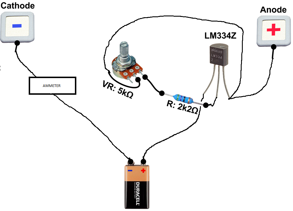
I do have R2 as 2k2 at the moment, look at the image this is exactly what I have now. It all works fine, just this question is there a way to make it start at 0 and with the potentiometer get it up to 3mA?
I am sorry for very child like image but, I am rubbish with this electronic schematics...

I do have R2 as 2k2 at the moment, look at the image this is exactly what I have now. It all works fine, just this question is there a way to make it start at 0 and with the potentiometer get it up to 3mA?
I am sorry for very child like image but, I am rubbish with this electronic schematics...
Re: Simple 2mA 9V circuit
An ammeter goes in series with the load (your anode to cathode), in your pic you have drawn it parallel across the load.
An ammeter can go in either the line to the anode or the line from the cathode to the battery.
You also have the LM334 back to front ie the +ve supply goes to the + pin and the anode (and potentiometer) connect to the - pin.
An ammeter can go in either the line to the anode or the line from the cathode to the battery.
You also have the LM334 back to front ie the +ve supply goes to the + pin and the anode (and potentiometer) connect to the - pin.

Last edited by Pauldf on Sun Nov 10, 2013 6:53 pm, edited 2 times in total.
-
fatetrader
- Posts: 12
- Joined: Fri Nov 08, 2013 4:03 pm
Re: Simple 2mA 9V circuit
I am a bit confused with the ammeter, it has 3 wires, red, black and green.
(red and black are the power for the ammeter)
red - I have connected to battery +
black - I have connected to battery -
so where should I connect the green one?
When I have changed the wiring on LM334z as you suggest ammeter wont display any values.
(red and black are the power for the ammeter)
red - I have connected to battery +
black - I have connected to battery -
so where should I connect the green one?
When I have changed the wiring on LM334z as you suggest ammeter wont display any values.
Re: Simple 2mA 9V circuit
Is it definitely an ammeter?
Re: Simple 2mA 9V circuit
Try connecting the green directly to the cathode (so it is the only wire on it), black to bat -ve and red to bat +ve.
-
fatetrader
- Posts: 12
- Joined: Fri Nov 08, 2013 4:03 pm
Re: Simple 2mA 9V circuit
Yes it is ammeter, look here it is this one http://www.ebay.co.uk/itm/370929093279? ... 1439.l2649, I tried connecting green to cathode and nothing