SCART Connectors

Description
21-way connector used to connect video equipment together. It provides connections for video input and output, audio input and output, RGB video and control signals (2 comms. data connections, blanking, function switching). In case you were wondering, SCART stands for 'Syndicat des Constructeurs d'Appareils Radiorécepteurs et Téléviseurs'. Also known as Peritel connector. SCART has largely been replaced by HDMI in recent years.
Typical Applications
Audio Video Equipment - TV, VCR, Satellite Receivers, Cable Boxes.
Home Cinema
Pin Assignments

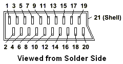
The diagram shows numbering of pins in connector, viewed from solder side of plug. Note that there are 20 pins, the 21st connection is the metal shell of the connector, to which the screening braid of the cable should be connected.
| Pin | Function / Direction (See Note 2) |
|---|---|
| 1 | AUDIO Output Right |
| 2 | AUDIO Input Right |
| 3 | AUDIO Output Left |
| 4 | AUDIO Ground |
| 5 | BLUE Video Ground |
| 6 | AUDIO Input Left |
| 7 | BLUE Video |
| 8 | Function Switching (See Note 1) |
| 9 | GREEN Video Ground |
| 10 | Comms.Data Line 2 |
| 11 | GREEN Video |
| 12 | Comms. Data Line 1 |
| 13 | RED Video Ground |
| 14 | Comms. Data Ground |
| 15 | RED Video |
| 16 | Blanking |
| 17 | VIDEO Ground |
| 18 | Blanking Ground |
| 19 | VIDEO Output |
| 20 | VIDEO Input |
| 21 (Shell) | Common Ground / Screen |
Note 1: Pin 8 provides function switching. Applying 9.5-12V to the pin will cause a compatible TV or VCR to switch to the AV (SCART) input. It may also switch on the equipment from standby. Applying 0V or leaving unconnected will switch back to TV. Some TV's also use this pin to select the aspect ratio. Applying 5-8V to pin 8 will switch to 16:9 mode. This may be used by DVD players to set TV to correct ratio. Connect ground to pin 14 or pin 18.
Note 2: Signal direction refers to the socket on a device, not the plug. E.g. audio output would be an output from the device. The other end of a cable connected to this socket would need to connect to an input. Follow the signal path through to be sure you are connecting outputs of one device to inputs of another and vice versa. A standard SCART cable should have the necessary lines crossed to allow interconnection of 2 devices.
Connector Assembly Instructions
Cable mounting plug / socket:
Connections are normally soldered. Check if you need to slide the gland cover onto the cable before soldering. Take care to avoid shorts between pins when soldering, some sleeving on the connections may be a good idea. Sleeve the screen to prevent it shorting to the other pins and to keep it tidy. The plastic shell normally snaps into place around the metal connector after soldering, and the cable gland then screws on to hold the assembly together.
PCB mount connectors:
If the connector has mounting holes, screw it to the board before soldering. Solder several pins and check the connector is flush with the board before soldering the rest.


