POWER SUPPLY PROBLEM WITH MSP430F2013 BASED CIRCUIT

Need help with a project? Trying to find a component? Post any general technical questions here.
Post Reply
Sbrok82
Posts: 2
Joined: Thu Jul 15, 2010 11:49 am

POWER SUPPLY PROBLEM WITH MSP430F2013 BASED CIRCUIT

Post by Sbrok82 » Thu Jul 15, 2010 11:51 am

Dear sirs,
thank's for the replies!

I try to explain better my problem.

The scenario is illustred at this image.
Image

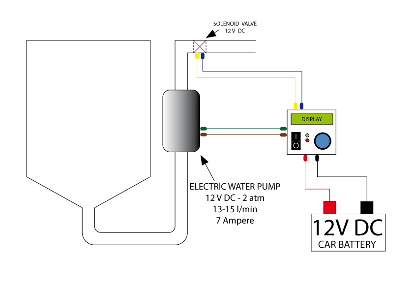
A water spot must be sprayed at the pressur of a pushbutton.
My power supply is a 12V DC car battery.
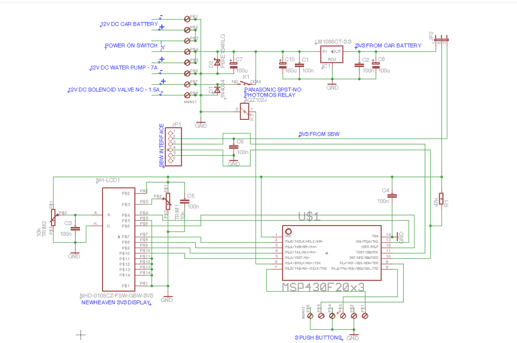
I made a circuit for control a 12V DC solenoid valve (the MCU control the relay) that must be open for some milliseconds (fig. 1).
A 12V DC water pump is used (and run "forever") for put in pressure the water pipe. The pump needs about 7 Ampere when running.
A linear voltage regulator is used for give 3.3V DC from the 12V DC car battery, used for supply the control circuit.

My problem born when I close the circuit, all start for 1 or 2 seconds and then the MSP430 and display retroillumination coocks!

I suppose this is caused by the water pump current consumption and I made a little change to my circuit (fig. 2).
Now I have a second 9V battery with a second power on switch that supply only control circuit and all seem to function correctly.

My question is: how I can obtain a safe 3.3V from the 12V DC car battery without all listed problems?

Thank you in advance,

Silvio Vallorani.

Image

Image

Simon (Webmaster)
Site Admin
Posts: 173
Joined: Tue Jan 29, 2008 7:05 pm
Location: Nottingham, UK
Contact:

Re: POWER SUPPLY PROBLEM WITH MSP430F2013 BASED CIRCUIT

Post by Simon (Webmaster) » Thu Jul 15, 2010 6:29 pm

Does the same problem occur with the pump disconnected? I'm wondering if the back EMF from the pump is causing problems. Check the voltage on the output of the 3V3 regulator with JP1 removed, both with and without the pump connected. I can't see any other obvious problems, since the solenoid output is isolated from the 3V3 circuitry, and the pump isn't controlled at all.

It might be wise to add a bit more decoupling - a 0.1uF ceramic capacitor either side of the regulator, close to it, and small electrolytic on the 12V input to the regulator. You could also try a diode (1N4001 or similar) before the electrolytic to isolate the supply from the pump and anything else on the 12V supply. If you have access to an oscilloscope check both the 12V and 3V3 supply for noise or oscillations.
Simon Carter
Electronics 2000
http://www.electronics2000.co.uk

Simon (Webmaster)
Site Admin
Posts: 173
Joined: Tue Jan 29, 2008 7:05 pm
Location: Nottingham, UK
Contact:

Re: POWER SUPPLY PROBLEM WITH MSP430F2013 BASED CIRCUIT

Post by Simon (Webmaster) » Thu Jul 15, 2010 6:32 pm

Also put a 0.1uF ceramic cap on the microcontroller supply pins - you seem to have an electrolytic cap (C4) but nothing to decouple high frequency noise. The datasheet for the micro might have some suggestions for this too.
Simon Carter
Electronics 2000
http://www.electronics2000.co.uk

Sbrok82
Posts: 2
Joined: Thu Jul 15, 2010 11:49 am

Re: POWER SUPPLY PROBLEM WITH MSP430F2013 BASED CIRCUIT

Post by Sbrok82 » Sat Jul 17, 2010 8:31 am

This is what I do. Can you take a look for me, please?

Image

Image

Simon (Webmaster)
Site Admin
Posts: 173
Joined: Tue Jan 29, 2008 7:05 pm
Location: Nottingham, UK
Contact:

Re: POWER SUPPLY PROBLEM WITH MSP430F2013 BASED CIRCUIT

Post by Simon (Webmaster) » Sat Jul 17, 2010 12:03 pm

Hi

That looks a lot more resilient, I can't see any immediate problems with it. The transzorb suppressor a good addition. Assuming that the photomos relay can be driven directly from the micro (I'm not familiar with them) all looks OK. Make sure the voltage of the electrolytic on the input side of the regulator is high enough (at least 25V) since automotive 12V supplies can be pretty unpredictable.

It would probably be wise to check the 3V3 supply voltage before fitting the LCD / micro (or at least before fitting a jumper on JP2).
Simon Carter
Electronics 2000
http://www.electronics2000.co.uk

Post Reply