
- Calculators
- Software
- Electronics Assistant
- EPE Index
- Evil Genius - Resistor Attack
- Stopwatch with split / lap time functions and 1 millisecond resolution
Links to more software can be found here.
- Technical Data
- Pin-outs
Connectors
- 12N / 12S (Used on trailers, caravans etc.)
- Banana (Used on test leads etc.)
- BNC
- Car Cigarette Lighter Connectors
- Coax (TV / Radio aerial connector)
- D Type (Mutipole, commonly used on computers etc.)
- DC Power Connectors (Barrel type)
- DIN
- F (Satellite etc.)
- FCC68 Modular Connectors - Used on telephones and computers.
- IEC (Mains "Kettle Plug" type)
- Jack (All sizes)
- Mini DIN (PS/2, S-Video etc.)
- N
- Phono (Audio Connector)
- P552/1 (8 pin as used on disco lighting etc.)
- R.F. Connectors
- RJxx (RJ45 etc. - Used on computer networks and telephones)
- SCART (Audio Video connector)
- Socapex
- Speakon
- TNC
- USB (Coming soon)
- XLR
Components
- Beginners Guide
- Forum
- Links
Categories
- Books
- Educational & Hobby Sites
- Components, Kits & Test Equipment
- Design & Manufacturing
- Products & Other Equipment
- Lighting & Sound
- Magazines
- Projects
- Software
Want to suggest a link to add here, exchange links with us or get a banner for your website?Click here for details.
- FAQ
- Contact


DIN Connectors

Description
Round, push-fit connectors available in 2-8, 13 & 14-pin versions, including 3 different 5-pin types, and 2 different 8-pin types. Line plugs, line sockets and panel mounting sockets are available. 3-8 pin types all have the same size shell, and some are interchangeable (e.g. a 3-pin plug will fit a 5-pin socket). A notch in the shell ensures the plug will only fit one way round. Most common is the 5-pin 'A' type, used for audio and computer keyboard connections.
Typical Applications
2-pin - loudspeaker connections
5-pin - audio line level input/output (e.g. 'tape'), keyboard (not PS/2)
8-pin - stage lighting control (6 channel 0-10V analogue)
13 & 14-pin - Atari computer equipment
Other applications requiring a low voltage mutipole connector
Mini versions of these connectors are also available - see here for data.
Pin Assignments
Note the odd pin numbering - designed so that the pin numbers stay the same regardless of the number of pins in the connector:

0-10V Lighting Control (8-pin):
| Pin | Pulsar Equipment | Strand Equipment Etc. |
|---|---|---|
| 1 | L.V. Supply (18-25V) | Channel 1 |
| 2 | Ground (0V) | Channel 2 |
| 3 | Channel 1 | Channel 3 |
| 4 | Channel 2 | Channel 4 |
| 5 | Channel 3 | Channel 5 |
| 6 | Channel 4 | Channel 6 |
| 7 | Channel 5 | L.V. Supply (-ve Strand, +ve others) |
| 8 | Channel 6 | Ground (0V) |
Low Votage Supply provided by dimmer packs etc. to
power controller.
Check with the manufacturers if in doubt as to which type of wiring your equipment uses.
Be careful when connecting equipment from different manufacturers.
Loudspeaker (2-pin):
Round Pin - Positive
Flat Pin - Negative
Computer Keyboard (5-pin Type A):
Pin 1: Clock
Pin 2: Data
Pin 3: Reset on old XT keyboards, otherwise unused
Pin 4: Ground (0V)
Pin 5: VCC (+5V from computer)
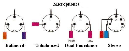
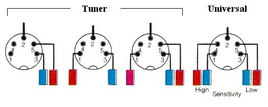
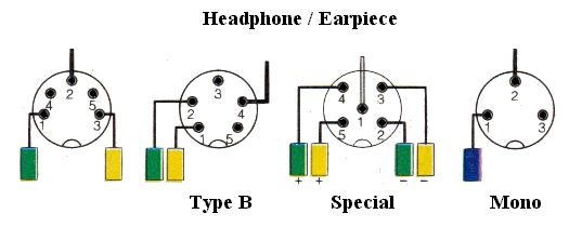
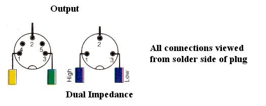
Audio (5-pin Types A,B,C):


Connector Assembly Instructions
Line Plug / Socket:
Normally solder connections. Thread outer cover onto cable, solder wires to pins, then assembly 2 halves of shell around connections and close cable clamp with pliers. Slide the plastic cover over the shell - a tab on the metal shell holds it on (you will need to bend the tab in to remove the cover again). 2-pin plugs/sockets may have screw connections and a push-on cover.
Chassis Socket:
Normally solder connections. It may help to fix the socket to the panel first to hold it steady.