Page 1 of 2
DPDT slide switch
Posted: Thu Oct 06, 2011 9:50 pm
by starcott
I have a Casio Keyboard of which I cannot get the power switch to work.
How can I test the switch to see if it faulty?
I have taken all the parts off the keyboard necessary to get to the switch and there is nothing obviously wrong with the switch.
It has 6 terminals all soldered into the circuit board.
When switched on, a red LED should indicate power 'on' but it remains unlit.
Power is provided by a 9v transformer or 6 batteries.
Can I connect a meter to any of the terminals of the switch to check for continuity? If so, which terminals?
Is it possible to describe what each of the 6 terminals should be connected to?
LED Power 'ON" indicator; how important?
Posted: Fri Oct 07, 2011 10:35 pm
by starcott
My Casio keyboard will not power up.
The switch is a DPDT slide which should switch on the red led when in the 'on' position.
If the LED has failed, will this prevent power getting to the keyboard?
Re: DPDT slide switch
Posted: Sat Oct 08, 2011 3:32 pm
by Simon (Webmaster)
Hi,
It is unlikely that a fault in the power LED would prevent the rest of the keyboard from working. Can you see from the circuit board if all the 6 pins are actually connected to anything? It is possible that only some are used. With the battery and mains adaptor removed, you can safely use a continuity tester across the pins, try all combinations with the switch in both positions (I'm assuming it only has 2 positions?). With the battery connected you could measure the voltage (meter on DC volts) between the negative battery terminal / connection to PCB and any points on the PCB to check if power is getting to them, again check with the switch in both positions.
If you could post a picture of both sides of the PCB (particularly the track side) I might be able to figure out the connections and suggest further tests.
Re: DPDT slide switch
Posted: Sat Oct 08, 2011 5:34 pm
by starcott
Thank you, Simon, for the reply.
__________
Viewing the switch terminals on the PCB: Left hand side from 1 4 Right hand side
2 5
3 6
___________
With switch in position 'on' , I get continuity when joining 2 to 3, 5 to 6, 2 to left terminal of LED and 3 to left terminal of LED
With switch in position 'off', I get continuity when joining 1 to 2, 4 to 5 and 3 to left terminal of LED.
I will attempt to post a picture of the PCB later,
John
Re: DPDT slide switch
Posted: Sat Oct 08, 2011 7:59 pm
by Simon (Webmaster)
That makes sense. I'm guessing that pins 1 & 4 aren't connected to anything (they will be connected to the battery supply when the keyboard is off). Troubleshooting steps:
1: Check the continuity between battery positive connection and pins 2 & 5. At least one of these should be connected, although it could be via a diode.
2: Repeat this with the battery negative connection.
3: Connect the battery or mains and measure the voltage from switch pins 2 & 5 to ground (battery negative) - at least one of them should be 'live' all the time.
4: Repeat this with pins 3 & 6 - one should be 'live' with the switch in the 'on' position.
If possible check the above both with the batteries and the mains adapter. Is the connector for the mains adapter on the PCB, or on wires?
Re: DPDT slide switch
Posted: Sat Oct 08, 2011 9:28 pm
by starcott
No connectivity between pins 2 and 5 to battery positive, or battery negative, or adapter jack positive or adapter jack negative.
The jack socket for the mains adapter is soldered onto the PCB. There are no wires.
Using mains connector, voltage from pin 2 to negative on adapter is .68 v.
Voltage from pin 5 to negative is also .68v.
With switch 'ON', voltage from pin 3 to negative on mains adapter is .68 v.
Voltage from pin 6 to negative on mains adapter is .34v.
Unable to check voltage with batteries as I don't have 6 batteries of the correct size.
Voltage across soldered terminals of mains adapter is 8.9 volts.
Re: DPDT slide switch
Posted: Sat Oct 08, 2011 9:57 pm
by Simon (Webmaster)
At least the adapter is working. Is there 9V or thereabouts on any of the switch pins? If not, I think you need to trace the 9V power tracks between the input connector and the switch to see what other components they go through on the way. Probably best to do this visually on the board, and use the meter to check voltages all the points along the way.
A picture of the board could definitely help.
Re: DPDT slide switch
Posted: Sun Oct 09, 2011 2:48 pm
by starcott

Voltage at the switch is 0.68.
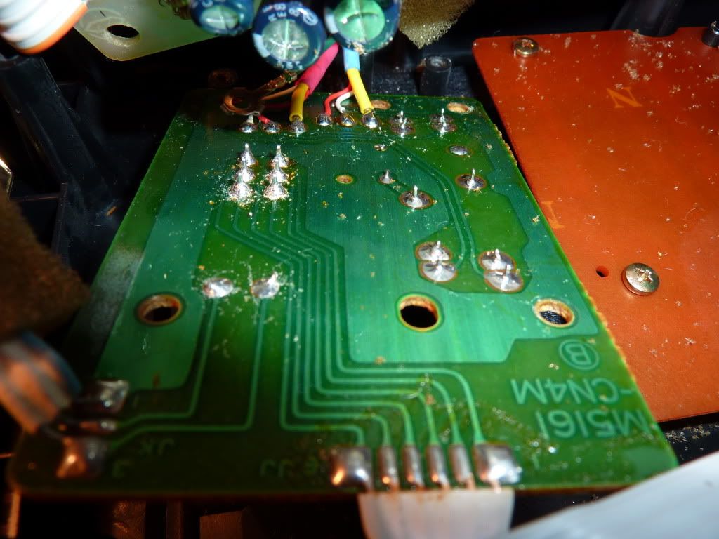
The input connector is on a PCB which is above another PCB holding the switch.
The top photo is of the upper PCB showing the 2 pins for the mains adapter at the top right. The 2 wires from the batteries are just to the left of the mains input.
Halfway down the right hand side there is a 3 core cable leading to the lower PCB, shown on the second photo.
The 3 core cable comes in on the bottom left of the photo with the switch in the background.
As the connecting wires between the 2 PCBs are short, it is difficult to get a good close view of the switch area.
Re: DPDT slide switch
Posted: Mon Oct 10, 2011 6:51 pm
by Simon (Webmaster)
Are any voltages present on any of the wiring connecting the two boards? I the input is on one, and the switch on the other, the unswitched supply almost certainly connects between the boards. No voltage on the interconnecting wiring would suggest the fault is on the input connector board, and vice versa.
Re: DPDT slide switch
Posted: Mon Oct 10, 2011 8:43 pm
by starcott
Had some real success tonight.
Managed to fit the 6 necessary batteries and the power came on.
I also tried another mains adapter and that works intermittently when the plug is moved about in the socket at the back of the keyboard.
So it now looks as if the problem is (a) I was using a faulty mains adapter, and (b) something needs resoldering in the area where the adapter socked joins the pcb.
I should now be able to sort this out.
Thank you for all your time and attempts to solve my problem.
John